DH2oon Ups and Downs.

Well, it’s been awhile, but as promised here are some images of the built-tested-and retired toonish WWI DH2. I really liked the way it came together,but it’s main weakness I was later to discover was its durability. The flimsiness of the “wickerumpf” design as the Germans referred to this latticetail structure in WWI, caused the wing incidences to shift and created a need for stabilizing wires (just like the originals ironically) which made the little machine more complicated and draggy than I originally intended. It flew decently, but only after extending the wing area and truing up the angles through wire stabilization. Alas, my goal is a simpler design, so off we go to greener pastures, namely a toonish Junkers WWI variant which will appear here shortly, and perhaps another 1930’s design that I might throw in here as well…..depending on its successful maiden.

These were taken after some pretty rough proving flights, the damage is unrepaired as I had determined at this point to retire her….you get the jist though at this point she has seen better days!


Some new items……..

Well, all has been moving forward of late, so much so however that I have been neglecting posting. So here we go. The Me 109 flew well, but only after installing a slightly larger powerplant. As with all designs that push the components to the limit of their abilities, some things can sneak past you. In this particular design it was wing thickness. There is a distinct relation between lift and drag, and for you budding airframe designers, this link can be mystifying at times. For instance, a more draggy WWI Taube design (see the Taube category to the right for an example) with flying wires and drag inducing details, flying on the same engine as the ME-109 design should be much draggier (and it is) than the clean 109 which is much more slippery and aerodynamically clean. So therefore, putting the exact same engine into the aerodynamically cleaner 109 of the same wingspan should result in its flying even better than the old draggy Taube…..right? Wrong….in fact, it wouldn’t climb out at all…..only do an extended glide into a belly landing every time. So why?  The answer…….wing thickness. I noticed after building the 109 that it had quite thick wing cross section. Now with plenty of power this can produce a huge amount of lift….but in hindsight, in designing for this smallish powerplant, I should have opted for a thinner wing. The thinner wing produces less lift, but the gained reduced drag was what this design needed for this powerplant, not more lift. Look at it this way….the ratio of drag that was contained in the thicker wing, although accompanied by the potential for more lift, would be the equivalent of (drastic example here…it is a bit more subtle really) to putting an all metal Cesna wing on a go-cart engine powered ultralight. Sure the wing will work….but this little guy hasn’t got what it takes to make it work…its small power won’t allow the wing to enter its correct range of operation. Long story short…..bad choice for this engine…..but not out of the ballpark completely. So I slapped a larger motor in…flew it….a friend saw it and fell in love and it got solded!!  So….enough on aerodynamics. Some new projects are in the works…..some ancient/primitive instrument creations…..and a new plane design that (is cartoonish!!) and I hope I can make simple enough to be buildable by others. The following image is a hint…..more to come.

airco-dh2

Some very cool cartoonplanes I’d like to introduce!

Well, considering I tinker with cartoonish style Rc aircraft on occasion (amongst other things), I happened across some very cool cartoon machines that I couldn’t resist turning folks on to. And not only do they fly well, (unlike some of my experiments!), but you can purchase and fly your very own, and at very minimal cost. The following images are of some of the cartoonish flyers that the kind folks at ParkFlyer Plastics offer.

OLYMPUS DIGITAL CAMERA IMG_4324

OLYMPUS DIGITAL CAMERA OLYMPUS DIGITAL CAMERA

They have all of these and more, so stop by http://parkflyerplastics.com/cart/index.php?main_page=index&cPath=24_62 and check em out. Then you can have something stubby and cute in the air too!

Scale fanfold Me109 Emil

So this is the latest, somewhat envelope pushing design. Being more traditional, (and very scale), we should be in a more success laden area. The only element of risk in the design is the quite small .049 Surestart in the nose. These don’t tend to like being cowled in, and this one certainly is. Lets hope the cooling elements incorporated ,such as the intra spinner fan, will help with keeping that little internal combustion engine running, and flying. Some shots:

IMG_7620IMG_7625IMG_7623IMG_7629

The first shot isof the Fiddlers Green Card model that this design is scaled up from. You can check the build thread at the following: http://www.rcuniverse.com/forum/m_11362320/tm.htm

Wow…..not again.

 Thomas Edison was purported as saying, when asked about the struggles involved in inventing the electric light bulb, that he failed at least 1000 times before he finally got it right. Also, when asked why he wasn’t discouraged during this process he stated (and I’m paraphrasing here) that he wasn’t disheartened enough to quit altogether because at least now he knew he was one step closer to success, because he knew one more way that it didn’t work, and was thus closer to solving how it would work. As much as I’d like to say that I believe he was that rosy during failure, or for that matter that the light bulb wasn’t just one more idea he “borrowed” from Nikola Tesla, I must say that for myself, the last few concept designs I’ve tried here have been, well, less than succesful. Granted they have had very narrow self imposed success parameters. The Mig is the latest. Intended to be used only with the one engine I had on hand, and very much like the Toon P-40, the engine was not up to the task, in the Migs case to handle all of the inherent drag of the design. She struggled, and just barely achieved flight, and remained low over the ground in an extended glide at best, without ability to climb away. Ah well….new things are already underway. Something more standard so we can have a bit of success for a change, but fear not, there are some envelopes still being pushed. The details will appear here shortly!

In the meantime…….

Well, flight tests on the little ducted fan are moving ahead. I wish i could say swimmingly, but its becoming apparent that the little guy is somewhat tail heavy. It tries to relate this to you by backflipping every time you try to launch it. Thank goodness I have a soft testing grounds, that being a soybean field nextdoor over which I am testing the little one. Long story short,more nose weight is needed. Let’s hope it doesn’t need so much(due to its short length) that it overwhelms the engines ability to fly the design. Time will tell.

As the title of this post indicates, “In the meantime” you may be interested to know that a similar design has been tried before, and in a full size aircraft that actually carried people. The Caproni-Stipa was built and tested before WWII by the Italians. Click below to see this oddity in action.

http://www.youtube.com/watch?v=xYqr2h_xQRk

As Solomon said a while back…..”There’s nothing new under the sun.”

……more to come re the little Toon-Mig soon. I also seem to be having an issue with the video link above. Will tweak shortly : )

Toon P-40 regress, and further top secret developments…

I regretfully must inform everyone that the Toon P-40, as beautifully as it came together and ended up looking, was a tad too large and too heavy for the Surestart powerplant for which it was designed. A slightly more beefy engine would’ve made her work, but my very narrow goal is to use the engines which I currently have on hand, so the Toon P-40 is retired at the moment. However, we have started another project intended for the same powerplant that will hopefully be a better fit and produce more satisfactory results. Top secret transmissions from behind the iron curtain have revealed that a Toon version of the following aircraft is under construction. More data will be released in the near future.  : )

Image

Ford Flivver Flies

Well, it’s been a while since I’ve gotten around to getting some of this stuff up on the site, so here we go. Here is what the Ford Flivver actually ended up looking like when completed.

Not too bad. The dummy Anzani engine heads really give it a scale presence.

And here is the video of one of the first proving flights.

http://www.youtube.com/watch?v=IjGIMdKZXyk&feature=youtu.be

It’s not the best quality as it was taken on a simple hat cam, but you get the basic idea. As was mentioned in the clip, I am experimenting with different prop sizes to try and cut the speed a bit to help with landing on my rough field.

All for now….but stay tuned as there are some Toon P40 pics detailing some of the progress made there coming soon.


Some Undercarriage details for a fellow Roland CII enthusiast.

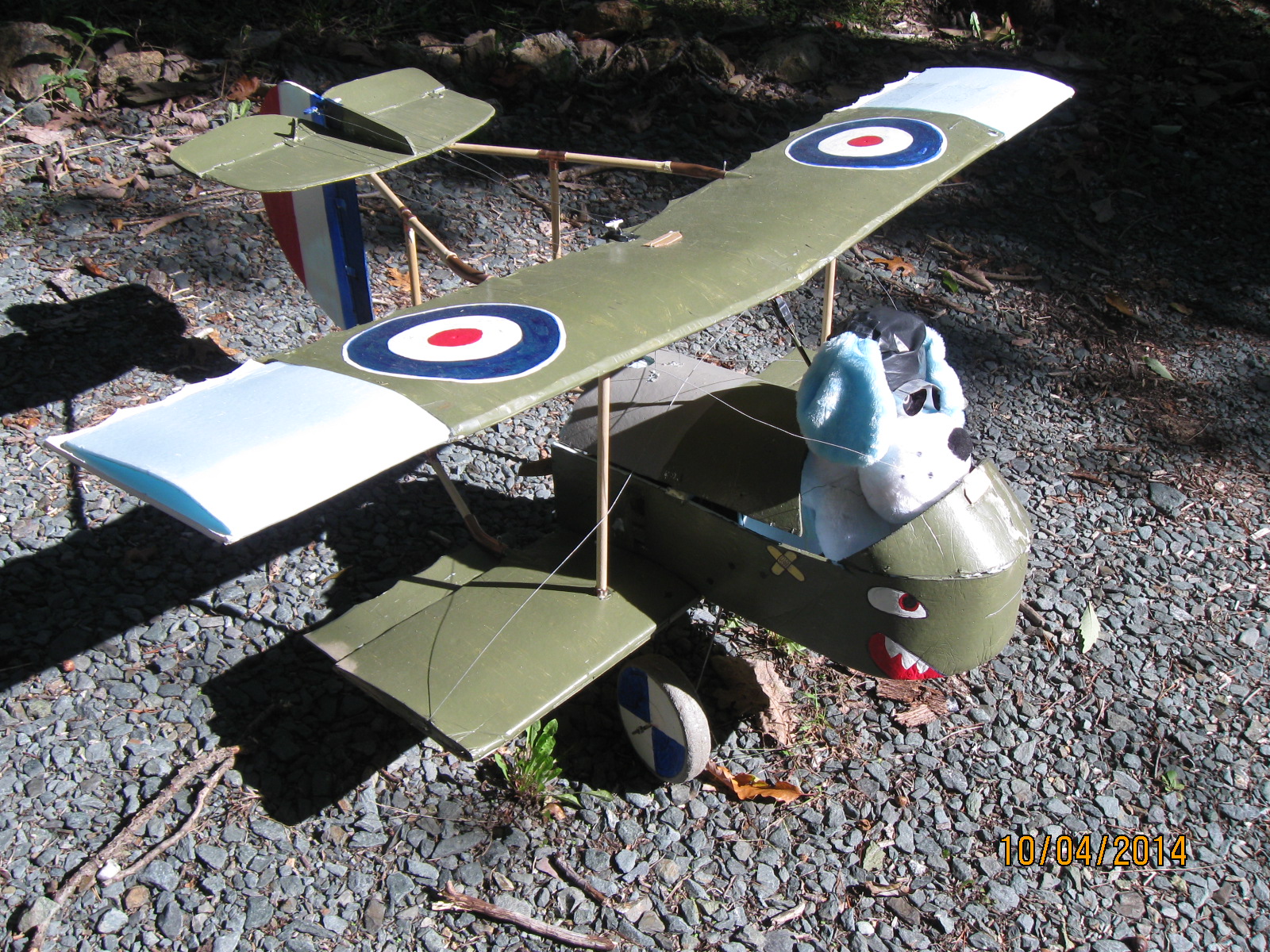
This is for Peter who is carrying forward the Roland CII tradition and building his own, around 50″ scale version. His will likely be more successfull than mine was, as he won’t be overloading it with too large an engine and fuel tank, so that it becomes overweight and flies like a pig…..thats been eating bricks…….for weeks. You can check out his comments so far in the Roland CII section all the way at the bottom of the page. I thought I’d move the conversation here though, as others might benefit from whats being discussed. We had been discussing undercarriages, and I did a quick sketch of the one I used on the Roland CII. Poor as it is, it is a picture, so maybe it’s worth 500 words, I wouldn’t wager a thousand.

The top is the type I used on the Roland. Since mine was so small, a little less than 30″, I couldn’t use the type on the bottom that I used on my larger sized WWI birds. So what you see is a steel wire “V” frame inserted into wood blocks inside the fuselage that are glued to bulkheads. You just drill the right size hole after shaping the v and insert the bent ends and(glue) them. Then you bungee the floating axle to the bottom of the “v” with an appropriate strength rubber band..(your discretion). The fairing is attached to the top of the axle, I used small copper wire on the bottom to fasten the fairing and glued it into the foam fairing by simply pushing it in with glue attached. Be sure the axle spins inside the three or four little wire loops. This way, when in place, the axle can bounce up and down, and the little indented ends of the fairing keep it level in action by contacting the v frame. I hope this makes sense.

The bottom example is great and authentic when you have a thick enough fairing (larger models) and simply uses streamlined aluminum tubing (with steel wire inside optional) for the frame. At the bottom a piece of tin or aluminum flashing is folded around the bottome and glued in place. In this with a drill, a vertical slot is cut for the axle. Another thin peice of flashing can be connected between the two underneath to join the two sides and act as a cover for the groove in the fairing. I usually add tabs to this by which I can use screws to attach the fairing. Once the axle is in place and the two ends bungeed, you simply slide the fairing down over the axle, ( I use foam so I simply cut a horizontal slot to accomodate the axle in the fairing) and attach it to the bottom cross member with screws. This way the axle bounces up and down inside the fairing.

Hope this helps, it’s a lot in a very small space. But if you have any questions please ask, and perhaps others have their own techniques they’d like to share! There is more than one way to do this.

C.